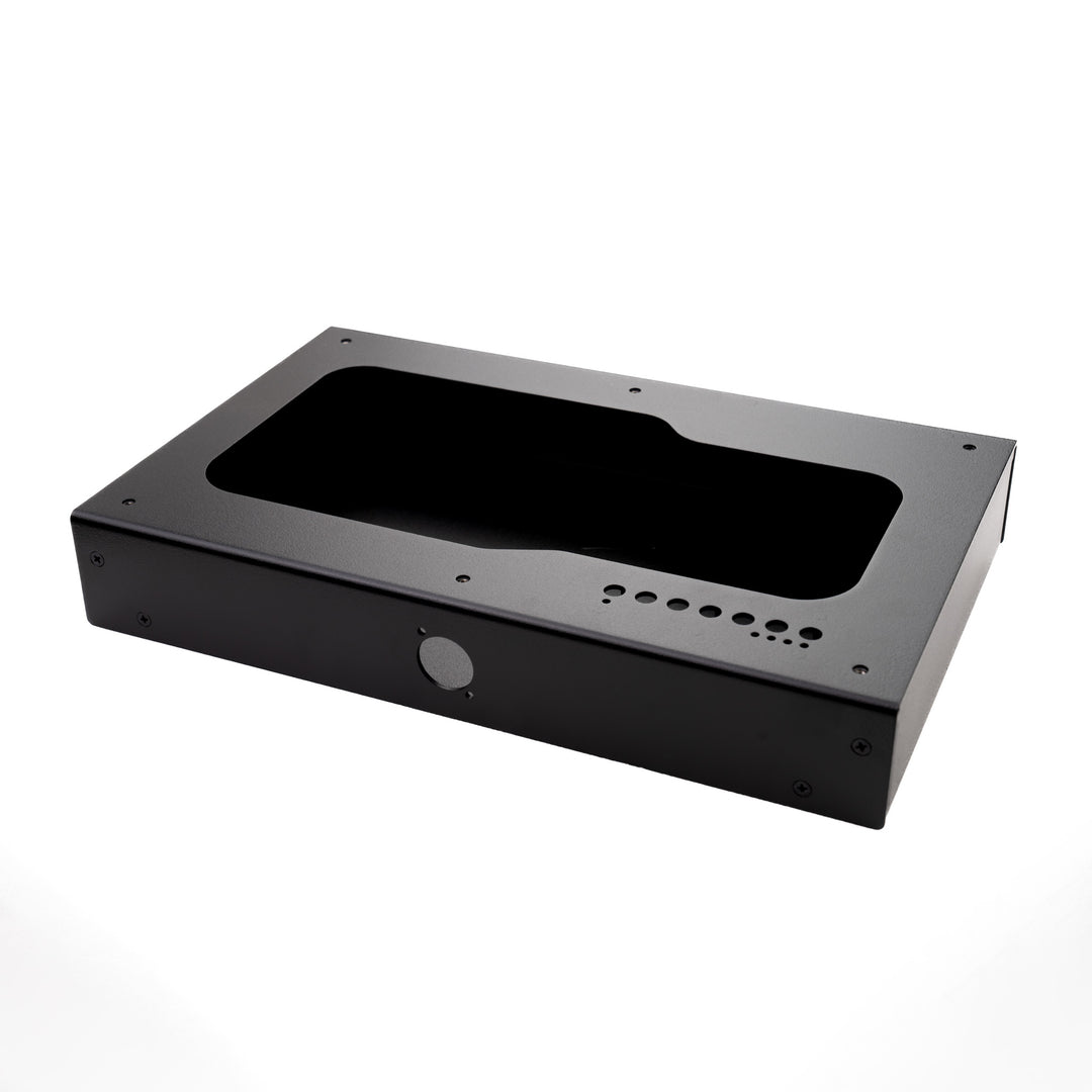

CPS2 Case Assembly - General Overview
Jasen's Customs CPS2 Case General Assembly Overview
This guide is meant to be an general overview only, not a detailed step by step guide as installation varies greatly by the final desired setup (With Digital A/V, without, etc.) If you have questions, do not hesitate to reach out via the contact form or visit our discord server. It's better to ask the question before you damage something that can't repaired or isn't covered under a warranty.
This is very much a DIY project that require some understanding of assembly, thinking through the overall build, and planning ahead. If you need detailed help, please reach out via discord in the CPS2 Case channel.
Ensure you have all the required pieces NOT included with the kit ahead of time. You will need to buy things, its listed on the product page. This includes but is not limited to: 12mm momentary buttons (that use a 11.5-12mm mounting hole), a right angle 90 degree pin header with 2.54mm pitch, a Digital AV Kit (optional), a Neutrik or Switchcraft D blanking plate (use it if you aren't using the digital AV Kit), A Neutrik or Switchcraft HDMI D passthrough (use if using the digital AV kit), case fan.
Tools required; screw drivers, soldering iron, solder, wire.
Powder Coating: Each case is powdercoated with a high gloss finish. This looks great but it does show every imperfection, small surface scratch, etc. Please be careful with your case. They are shipped within acceptable standards for the finish, but if you scratch it or chip it due to dropping a tool on it during assembly, we can't be held liable for that.
Each screw hole, stand off, etc. is plugged with a little plastic bit before powdercoating. They too get some powder on them and this may leave small flakes or "high" spots around fasteners. This is normal and if it flakes free, that's OK. It bonds to the metal, so unless you try to peel it off or chip it off, you shouldn't see it come off metal parts of the case.
The powder is fine, so it could end up getting on some threads. Since the screws are stainless steel, it should clean away any powder that gets past the plastic bit. If its tight, thread it in slowly and back it out. Do this a couple of time and it should degall the threads. Do not over tighten anything, cross thread screws, etc. If you feel resistance, stop. Make sure you have the right screw, and try again. Damage to threads during assembly due to user error aren't covered.
Screws and Hardware Included:
- M3 screws, 11 of them. Used to hold the A board to the case.
- M3 plastic washers, 11 of them. Used just under the M3 screw head to offer separation between the PCB and the screws.
- 3D printed (PLA) spacers, 11 of them. Place over the stand offs where the board sits to ensure it doesn't slip over the stand offs due to manufacturing tolerances of the PCB holes.
- #4-40 screws, 4 of them. Used to hold the screen/button board to the front of the case.
- #6-32 rubber feet, 4 of them. Used on the bottom of the case, threaded into the pressed in nuts.
General Install and Plan:
- Organize your hardware in groups to ensure its all easily accessible and accounted for.
- Inspect the case for signs of damage, this includes major dents, dings, large deep scratches. Fine, surface scratches or tape / packing material residue may be present but can be cleaned off with a soft rag and Windex. Paper towels or terry cloth may be abrasive. Use caution if using them.
- Open the case and clean out any debris left over plastic plugs.
- Ideally, you prepped your screen board ahead of time by removing the 14 pin vertical header and installing the right angle header.
- Install the screen using the #4-40 screws.
- Install the 3x 12mm buttons you supplied to the front of the case. You may need to "thread" them in. Do not force them in. The holes are 12mm before powdercoating, the powdercoat will remove about .01 - .03mm from the overall size of the hole; which is expected. DO NOT DRILL THE CASE - THIS IS NOT COVERED AND IMMEDIATELY VOIDS ANY WARRANTY.
- Put the plastic spacers on the stand offs on the bottom half of the case.
- Place the A board in place and secure using the M3 screws and M3 washers. Install the screws loosely at first, get the board situated, then fully tighten down.
- The B board will fit into place on the A board with the friction fit connectors along each long side.
- Install the fan on the top half of the case. You will need to wire it to the A board. Please consult the wiring diagrams for CPS2 boards and the fan you chose. This is completely situation dependent and I can not offer wiring recommendations here.
- You will want to solder a wire to each button on the A board, for TEST, VOL UP, and VOL DOWN. One leg of each switch is the signal and one leg is GND. You will need a signal and ground connected to each of the front switches to ensure these function. Please consult your favorite soldering guide on this process. If you are not comfortable with soldering, please ask a pro to help you.
- Install the HDMI pass through on the back of the case, or the blanking plate - which ever is appropriate.
- Install the 12mm switches on the back of the case to close the holes, even if you aren't installing a Digital AV kit.
Darksoft Kit Assembly:
Please refer to their official documentation and videos.