The Frame Design Guide

Welcome to THE FRAME design guide, contained within is all the important details you need for designing your custom Top Panel for THE FRAME. The files provided are for non-commercial use only. Please use them to design your layout and top panel to fit onto your new FRAME. You can submit any of the following file formats for custom cut top panels:
- DXF
- AI
- SVG
Files not in this format will be rejected as they are not considered "cutable". Over time we will add video guides to show the best way to design new templates and share them with other members of the community so we can build a large repo of great layouts. Our Discord is a great place to share templates and ideas you come up with. We highly encourage members share and offer design services to the community to make this as accessible as possible. JasensCustoms.com will offer design services at a rate of $50 per hour with the caveat that any files created will be shared with the community upon approval.
In the provided files you will have access to all the plexi sides, top, and bottom and can customize them all.
On each piece there are mounting holes and some 24mm holes for buttons. Please take the follow into consideration:
- Do not remove any mounting holes (the small ones) from the side panel plexi templates.
- Do not move any mounting holes. If you move them, your plexi will not attach to your FRAME properly.
- You may remove the center mounting holes on the top and bottom panels if you want.
- On the side plexi pieces, any of the 24mm holes can be removed if you do not intend on using those cutouts. By removing them the plexi will cover up and hide unused holes.
You can make your top panel and bottom panels larger than your FRAME and have overhang - creating some cool shapes and possibilities for your FRAME. If you add a significant amount of overhang, you may want to consider using some 51mm long support hardware to prevent flexing. There are a lot of creative ways to do this from 3D printed parts to aluminum extrusion. Just keep in mind you will need to provide mounting hole cutouts on your plexi (top, bottom, and inner pieces) to ensure you have a place to feed non-standard hardware.
The Top and Bottom Panel has two layers.
The outermost layer is 1.5mm and can be done with printed plexi or any of our standard colored plexi available.
The inner layer is 5mm and will be done with clear, black, or white acrylic based on your choice.
Top Outermost layer (1.5mm):
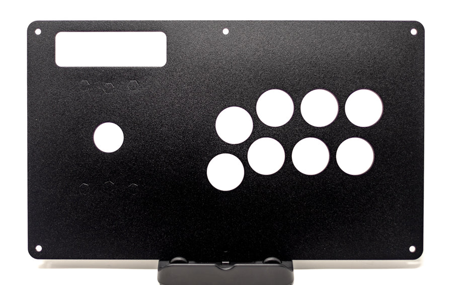
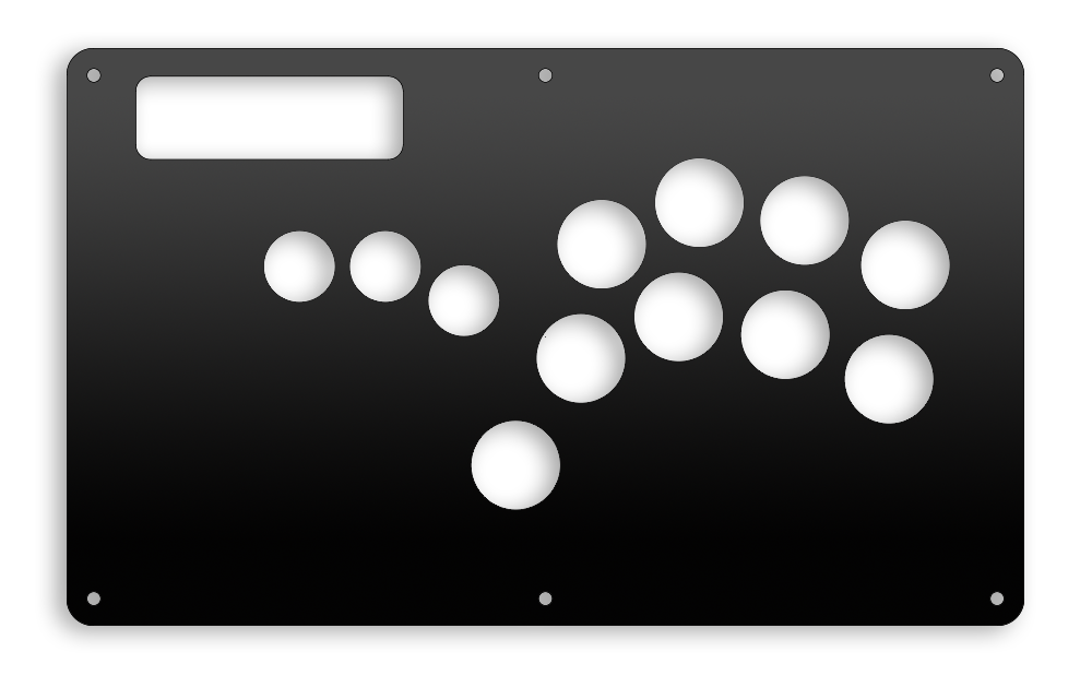
- Place your buttons and joystick in an arrangement that makes sense for you. You have complete control here. Keep your layout inside of the red lines dashed lines to ensure your buttons will not hit the FRAME. You must ensure all required mounting hardware is accounted for. We will not add or alter files submitted. We cut what you send.
- The Blue Dashed lines represent how far the average 24mm button will extend into the case. You can get close to these if you need to, just be advised that wiring may get tight in those areas.
- If you do not want to add countersinking to the inner layer for lever builds, please ensure your mounting hardware holes for the lever you are using is on the top outer layer.
- Ensure you keep the M4 mounting holes in tact on the outermost layer per the above guidelines.

Top Inner Layer (5mm):
- Duplicate all of your cuts from the outermost layer to this inner layer.
- You will want to create offset cuts for all of your buttons. 6.5mm is too thick for non screw in buttons to latch onto. I find that using a 40mm hole for 30mm buttons on the inner panel is sufficient for snap ins. 42-45mm is great for screw in buttons. (34mm and 36mm for smaller 24mm buttons). You can use the centers of your top layer holes to do ensure they are perfectly aligned. Once you create them all, you can remove the button cutouts on the inner layer they won't be needed.
- You do not and should not create offsets for any mounting hardware on this layer.
- For a nominal fee we will countersink lever mounting hardware on your inner panel using a drill press. This is done after its laser cut to ensure perfect placement.


This a perfect inner and outer layer. There are no extra cut lines on the inner layer. The customer used the pathfinder tool in illustrator to remove overlapping cut lines (or a power trim tool in Solidworks) to create one smooth contour cut for the inner panel. They are larger than the button holes to allow snap-ins and screw-ins to properly hold onto the 1,5mm top.

This is not per the design guide. The inner and outer layers are the exact same. You will not have a solid connection with snap-ins and they may pop out. Screw-ins may work, but they wont have enough threads engaged to stay tight long term. Fix the inner layer.
The Bottom Panel - Inner and Outer pieces
These should be mechanically identical. If you make the bottom a different and larger shape than the rounded rectangle that is standard, just ensure both are the same. If you only submit one file for the bottom, we will cut both the 1.5mm and 5mm pieces the same. If you have a special need for the inner panel to create additional clearance, its OK to put cutlines on the inner panel.
JasensCustoms.com is not responsible for checking your design files if they do not fit, its due to something you did. We cut what you provide.
Sharing with the community
Please feel free to start a thread in our Discord with your files so others can use them, modify them, or create their own using yours as inspiration. We ask that you do this in the following manner:
- Start your own thread and include the layout in the title. For example: "JasensCustoms - Sega Player 2 Standard Width Top Panel" is an acceptable title. Using "Yo, check out this crazy layout" is not. They should be easy to read, attributable, and searchable.
- Include a picture of your layout so people can see it right away without opening any files.
- Include DXF files for the layout in your post at a minimum. These are widely compatible with Adobe Illustrator and CAD Software. We encourage creating an AI file as well to support printed plexi runs and helping those with no CAD experience.
- Consider creating a 600 DPI, CMYK PSD template for it and sharing it as well. Many artists prefer working in Photoshop over Illustrator.
Resources
- SlagCoin - the most popular arcade layouts.
- Sanwa JLF Mounting Points: 84mm x 40mm rectangle. One hole in each corner. Center hole is 24mm.
- #6-32 screw diameter: 3.51mm - use 3.6mm to be safe.
- M4 screw diameter: 4mm (metric is great) - use 4.2mm to be safe.
- 30mm buttons: use 30.1 - 30.2mm to be safe. Using an exact 30 is OK but may add stress to the body.
- 24mm buttons: use 24.1 - 24.1mm to be safe. Using and exact 24 is OK but may add stress to the body.
The FRAME files:


